Added
the " Lower lateral link, upper
reversed A-arm,
twin trailing links rear suspension.
Thanks to Simon for this
one
RETURN
TO SUSPROG3D HOME PAGE

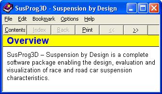
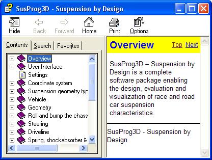
SusProg3D
- Suspension by Design.
===================
Version
4.510 adds additional functionality and a few bug fixes.
Thanks to all of those who made comments and suggestions.
In no particular order.
 |
Added
additional set ups for double A-arm front suspension to allow for both
upper and lower A-arms to be either "actual" or "virtual" A-arms.
Thanks
to Jason for this one.
RETURN
TO SUSPROG3D HOME PAGE |

===================
Version 4.505 has a number
of enhancements.
Thanks to all of those who made comments and suggestions.
In no particular order.
|
Improved
the performance for semi-trailing arm bump and droop calculations.
|
|
The ride height locations
have been updated to allow for specifying LH or RH location.
|
|
The
layout of the ride height data in Excel has been updated to include all
the LH and RH alternatives.
The help file has been updated with the
new details, particularly the layout and number of cells required.
Thanks
to Howard for this one.
|

===================
Version
4.504 adds additional functionality.
Thanks to all of those who made comments and suggestions.
In no particular order.
|
Addition
of recirculating ball steering for IFS where the tie rods connect directly
to the Pitman and idler arms.
|
Version 4.504B.
|
Fixed
a bug that caused semi-trailing arm bump calculations to fail .
Thanks
to Leonid and Osvaldo for this one. |
RETURN
TO SUSPROG3D HOME PAGE
 ===================
Version
4.503 adds additional functionality and a few bug fixes.
Thanks
to all of those who made comments and suggestions.
In
no particular order.
|
The
major enhancement is the addition of longitudinally located drag link steering
for front live axle.
Thanks to Derek for this
one.
|
|
For
both lateral and longitudinal drag link steering the Pitman can now be
positioned as required when in the steering is in the "straight ahead"
position.
|
|
For
both lateral and longitudinal drag link steering all calculations now now
be done with the wheels turned.
|
|
For
both lateral and longitudinal drag link steering the steering calculations
now include the "toe out in turn" data. |
RETURN
TO SUSPROG3D HOME PAGE

Version 4.502 has a number of enhancements.
Thanks to all of those who made comments and suggestions.
In no particular order.
The mounting
point of suspension items (shock, spring, pushrod, antirollbar) on an A-arm
can now be referenced from either the A-arm chassis pivot axis or from
the A-arm apex.
Additionally, the mounting point can now be referenced
from either the front or the rear A-arm link.
Thanks to Steve
at GRM for this one.
The mounting
point of suspension items (shock, spring, pushrod, antirollbar) on a link
can now be referenced from either the chassis pivot or from the suspension
pivot.
Added Front,
Left, Rear, Right and Plan view orientation buttons to all menu tabs.
RETURN
TO SUSPROG3D HOME PAGE

Version 4.501 has a number of enhancements.
Thanks to all of those who made comments and suggestions.
In no particular order.
Windows 7 Professional
is now correctly identified.
Thanks to Ian for this one.
When using the
Windows "Aero" display functionality, the graphic screen copy function
didn't work.
The screen copy function can be accessing using
either F6 or Control-C.
bullet With a virtual a-arm the front
and rear links were not correctly identified, and the calculation failed.
Addition
checks and error messages added to check this.
Thanks to Peter
for this one.
Added 4 leading
link front axle suspension.
Added all the lateral location options
- Panhard rod, Watts and Mumford linkages for front solid axles.
Thanks
to Derek for this one.
Enhanced the
recirculating ball steering to provide a way of specifying the Pitman arm
offset.
Previously the Pitman arm was always positioned either
straight forward (or straight backward).
Now the Pitman arm can
be specified with an offset to enable it to be angled either inwards or
outwards as required.
Thanks to Peter for this one.
Added a marker
to indicate the chassis CofG location.
Thanks to Rob for this
one.
V4.501B (Build 724.1)
Corrected a problem
calculating trailing arm suspension types.
Thanks to Gabriel
for this one.
RETURN
TO SUSPROG3D HOME PAGE

Version 4.500
Thanks to all of those who made comments and suggestions.
In no particular order.
|
Added
option to draw the undertray.
Although undertray input was added in
V4.84A it was limited to the PitchCentre calculations and not included
as part of the graphic display.
|
|
Added
option to draw the chassis datum plane. |
|
Added
a tool to create the chassis datum from vehicle coordinates.
Previously
the chassis datum could be relocated longitudinally and/or vertically.
This
adds the ability to create the chassis datum in any position, including
side rake. |
|
The
major enhancement is the ability to specify three ride height control points.
This
means that the chassis can be positioned with rake in both side and end
views.
Three points are used for ride height reference - two at one
end of the vehicle, and one at the other end.
The previous method only
allowed for two points to be specified |
V4.500B (Build 710.1)
|
Updated
SusProg3D Licence Server (Sawdust) to better handle TCP/IP messages. |
Version 4.91 adds additional functionality and a few
bug fixes.
Thanks to all of those who made comments and suggestions.In
no particular order.
|
Added
a File -> New option. |
|
Reorganised
the Excel export/import functions.
There are now four Excel
functions - two export functions and two import functions
“Calc2Excel”
exports the calculated data,
“Input2Excel” exports
the input data,
“Excel2Input” imports the input
data, and
“Excel2CMM” imports the CMM data.
In addition, the worksheet
naming has been extended to include "LH" and "RH" suffixes, and the various
calculation functions will now update the appropriate "Front" and "Rear"
worksheets.
A new tutorial Creating
Excel worksheets for LH and RH data has been added showing how to use
the worksheet names.
Thanks to Ben, Pesek and
Lloyd for these. |
|
Changed
the Ackermann distances and percentages to always relate to the front axle.
Thanks to Peter for this
one. |
|
Allow
for a strut suspension to have a separate spring.
The '79-'04 Mustang has
a modified Macpherson strut with the coil springs inboard of the struts.
The
'05 Mustang reverted to conventional strut mounted coil springs.
Thanks to Lonnie for this
one. |
|
Reorganised
the toe out in turn results to better fit on the printed page.
Thanks to Peter for this
one. |
Version
4.90 adds additional functionality and a few bug fixes.
Thanks
to all of those who made comments and suggestions.
In
no particular order.
<>
|
Updated
and added some additional functionality to the recirculating ball steering.
Allow
for the tie rod pivots to be either side of the track rod.
Add the
steering box ratio and overall steering ratio calculations.
Add the
option to specify track rod pivots with chassis coordinates, and back calculate
track rod offsets.
Thanks to Bruce and his Datsun1600 for these changes.
|
<>
|
Add
an option for the torsion bar to extend in either direction from the actuation
point, and for a defined chassis mounting point not on the wishbone pivot
axis.
Thanks to Chuck and his Porsche 911 for this one.
|
<>
|
Add
a note to the help file explaining how the motion ratio calculations are
affected by the wheel alignment.
Thanks to Simon for pointing this
out.
|
<>
|
Allow
for a second shock with a live axle four link.
Thanks to Louie and
his off road racers for this one.
|
<>
|
Renamed
the menu items from “Export2Excel” and “Import2Excel”
to “ExportExcel” and “ImportExcel”.
|
<>
|
Allow
for Windows 7.
|
<>
|
Compiler
upgrade, D2009 Update 2.
|
V4.90B
(Build 675.1)
<>
|
Updated
the maximum turn angle from integer to float and added a turn radius calculation.
Thanks
to Pratap for this one.
|
===================
Thanks
to all of those who made comments and suggestions.
In
no particular order.
<>
|
Added
the IMCA live axle with 4-link birdcage.
The axle
is located longitudinally with 4 trailing links. These links attach to
a birdcage which is free to rotate on the axle tube (and is restrained
axially).
To hold the axle in alignment, a torque arm extends forward
from the axle and is connected to the chassis with a link (which may be
a combination of spring and damper).
The axle is laterally located
by either a Panhard rod or a Watts linkage.
The brakes
are attached to the axle.
The usual
springing is with a single coilover shockabsorber attached to the birdcage. |
V4.89B
(Build 659.1)
<>
|
Fixed
a bug when using a-arm mounted toe control link. The mounting point wasn't
shown correctly when referenced from the front mounting point.
Thanks
to Pesek for this one.
|
Version
4.88 has a number of enhancements.
Thanks
to all of those who made comments and suggestions.
In
no particular order.
<>
|
Added
a crossmember tool.
Older unit body sedans and contemporary hot rod
conversions often use a separate chassis crossmember with a-arm, spring
and steering mounts.
This tool maps the coordinates between the crossmember
and the chassis.
Thanks to Mick for this one.
|
|
Added
a nominal curb-to-curb turning circle (all steering types) and the number
of steering wheel turns lock to lock (for rack and pinion steering).
Thanks
to Mick for these. |
<>
|
Added
the roll gradient to the dynamic calculations.
Thanks to Rupert
for this one. |
<>
|
Fixed
a bug that prevented the suspension travel being set by specifying the
shock open and closed lengths if the spring dialog was open at the same
time.
Thanks to Roger for this one. |
 Version 4.87
adds additional functionality and a few bug fixes.
Version 4.87
adds additional functionality and a few bug fixes.
Thanks to
all of those who made comments and suggestions.
In no particular
order.
<>
|
Added
a stand alone spring calculator. Available in the Tools menu.
Handy
for those times when you have a spring and just need to know the rate.
|
<>
|
If
the Antirollbar Correlation Factor was zero, this caused the antirollbar
calculations to fail. It now defaults to 1.0
Thanks to Gavin for
this one.
|
<>
|
Added
an option to the wheel alignment settings to allow for specifying the toe
in degrees. Typically, laser toe gauges have a resolution of 1/60th of
a degree, approx 0.02 degrees.
|
<>
|
Updated
the registration algorithm for Vista.
|
<>
|
Added
"double ball joints" to the CMM tool for struts.
Thanks to Mark
for this one.
|
<>
|
Added
the upright coordinates referenced back to the chassis datum. This is makes
it easier to position suspension component in the correct place when the
chassis is in the chassis jig.
Thanks to Tim for this one.
|
 Version
4.86 has a number of enhancements. Version
4.86 has a number of enhancements.
Version
4.86 has a number of enhancements.
Thanks
to all of those who made comments and suggestions.
|
Updated
driveshaft configuration.
For those suspension types
that use the driveshaft as a suspension link it is now possible to specify
the driveshaft as "Fixed length driveshaft (top lateral link)" or as "Variable
(splined) or "Variable (plunging joint)".
When the driveshaft is
specified as "Fixed length driveshaft (top lateral link)" the driveshaft
will act as the top lateral link.
This is the typical arrangement for
Jaguar and Corvette rear suspensions.
When the driveshaft is
specified as "Variable (splined) or "Variable (plunging joint)" then the
driveshaft will not take suspension loads, and a separate top lateral link
is required.
Thanks to Toni and the
Finnish Corvette community for this one.
|
|
Upright
camber shims and steering
When upright camber shims
are used, and they also adjust the steering arm, then this is now noted
in the steering results.
Thanks to Jan for this
one.
|
|
Dynamic
parameters
The dynamic parameters
now include a Vehicle or Custom option to determine the input data. This
provides a clearer distinction between using the current vehicle parameters,
and bespoke "what if" parameters.
Thanks to Rupert for this
one
|
|
Undertray
Fixed up the names on
the undertray input.
Thanks to Ian for this
one.
|
|
Wheel
spacer
Added a wheel spacer.
Thanks to Roy for this
one.
|
Version
4.85 has a number of enhancements.
Version
4.85 has a number of enhancements.
Thanks
to all of those who made comments and suggestions.
In
no particular order.
<>
|
Added
an anti-roll bar configuration to suit live axle with leading arms.
TThanks
to Pratap for this one.
|
|
Corrected
the motion ratio calculations for the fully floating shock and bellcrank
setup.
Sometimes the spring data displayed the wrong units.
Updated
the help file with additional notes about naming ranges for front and rear
sheets.
Thanks to Rupert for these. |
===================
Version
4.84 has a number of enhancements.
Thanks
to all of those who made comments and suggestions.
In
no particular order .
<>
|
The
existing pitch centre calculator will be deprecated. It will be removed
shortly.
|

Version
4.83 adds additional functionality to the dynamic calculations.
Thanks
to all of those who made comments and suggestions.
In
no particular order.
<>
|
The
dynamic calculations can now be done over a combination of front roll centre,
rear roll centre and lateral acceleration.
|
<>
|
The
dynamic calculation results can now be exported to Excel to enable a better
analysis of when calculating over a range of roll centre positions and
lateral accelerations.
|
<>
|
Added
an option to allow for a pushrod bellcrank to actuate from the top wishbone |
===================
Version
4.82 adds support for Microsoft Vista.
Thanks to all of those
who made comments and suggestions.
In no particular order.
<>
|
SusProg3D
is now supported on Windows Vista.
This has required several
changes to the SusProg3D installation, and to the help file.
Vista has greatly increased
security relating to User Access Control (UAC) and imposes more restrictions
on data file locations.
This has required changes to the install procedure.
This also affects installs on all other Windows versions.
Also, with Vista, Microsoft
have dropped support for the traditional WinHelp format, and now only support
the CHM (Compiled HTML) format.
To support Vista, the SusProg3D help
file has been converted from WinHelp to CHM help.
When upgrading older
versions which used WinHelp the patch files will include the new CHM help.
How do I know what style
of Help I have?
Start SusProg3D and then
go to Help -> Contents.
If
the help displayed looks like this, it is WinHelp
If
the help displayed looks like this, it is CHM help.
|
|
I
have added a "Correlation factor" to the antirollbar rate calculations.
Use
this to factor to adjust the calculated rate to match the actual rate.
Thanks
to Norm for this suggestion |
V4.81A
(Build 593.0)
SusProg3D Licence Server Phase 1
Driveline
data added to Excel exports.
V4.80A
(Build 586.0)
The basic geometry for a three-wheel configuration
has been added.
The currently supported configuration allows for two
front wheels (wishbones or strut) and a single rear wheel on a trailing
arm (essentially the same as a motorcycle rear suspension).
Thanks
to Gary for this one.
A
tool to calculate the wheel camber change over the range of upright shims
has been added.
Thanks to Oscar for this one.
For those
who usually work on the same data file, the last used data file will automatically
load when SusProg3D is opened.
Go to Settings |Settings and tick "Start
with last working file".
The "toe out in turn" calculations have been
extended to calculate caster trail and kingpin offset.
If you are exporting
"toe out in turn" to Excel, then increase the Excel range with an extra
four columns (a total of 21 is now required) to include the caster trail
and kingpin radius data.
If you do not
increase the Excel range, the "toe out in turn" data will still export
OK, just the caster trail and kingpin radius data will not be included.
Thanks
to Daniel for this one.
The
roll and bump results now include caster trail and kingpin offset.
Thanks
to Daniel for this one.
Version
4.78
Added graphic display print function.
Increased
the steer angle in toe out in turn calculations.
Increased the suspension
travel for trailing arm suspensions (especially for off-road vehicles).
Clarified
the exporting of brake and acceleration "anti" values to Excel.
Version
4.74
When drawing
the steering arm, also draw the king pin axis.
Added an "ungrounded"
toe control link to the rear A-arm suspension types. This is where the
toe control link attaches to the A-arm instead of the chassis.
Thanks
to Peter Davies for this one.
Fixed the Mumford
bellcrank axis offset dimensions so they always refer to the bellcrank
axis (and not the lever axis).
Add dual rate
coil-over springs.
Thanks to Ted Mitchell for this one.
There is now
a graphic display of the spring rate with the bump and droop travel positions
marked. This is especially applicable to the new dual rate springs and
hopefully will make the design and selection of spring rates easier. The
calculations are a bit complicated, and tend to require an iterative approach.
For metric
users, spring and wheel rate calculations have been brought in line with
SAE J916 “Rules for use of SI (metric) units”. This
means that spring and wheel rates will now be shown in N/mm rather than
kg/cm, and spring loads will be shown in N (Newtons). There is only a 2%
difference between N/mm and kg/cm, with the N/mm value being slightly smaller
than the kg/cm value for the same rate. The results will continue to show
rates in both N/mm and lb/in, and loads in N, kg and lbs. Vehicle “weights”
will remain in kg. For imperial users there is no difference. Rates will
be in lb/in, loads and weights in lb.
Removed some
code that was specifically for Windows 95 and added a note to the FAQ describing
the required fix.
Added the necessary
changes to support Windows 64-bit operating systems.
Thanks to the
V8 Supercar team for their patience and help on this one.
Added an “Update
Reminder”. This will pop up a box when the installed version
is 90 days old, and then once every 30 days, reminding you to check the
web site for program updates.
Added a camber
adjustment shim option for uprights.
Thanks to James Morrison for this
one.
Added the functionality
to set page margins for hard copy printouts.
Thanks to Jan Hoel for
this one.
Extended the
“toe out in turn” calculations to do both turn directions
at the same time. Also included the actual “toe out in turn”
angle and the caster data.
Thanks to Paul Yaw for this one.
Added the extended
“toe out in turn” data to the Excel exports.
Thanks
to Rob Palermo for this one.
When doing
a geometry calculation with the front wheels steered, the steer direction
is now independent of the chassis roll direction. Previously the turn direction
determined both the chassis roll direction and the steering direction.
The “straight ahead” wheel alignment toe settings are
used to return the steering to the straight ahead position, and to ensure
that subsequent calculations always start from the “known position”.
When doing a steered calculation, the wheel alignment dialog box will always
show the steered wheel alignment.
Added a graphical
isometric representation to the upright dialog. And when you click on a
pivot point, the name of the point and the co-ordinates will display.
Added extra
calculated info to the mass dialog. It now calculates the left and right
mass distributions as well as the percentage splits for the individual
wheels.
Added extra
calculated info to the centre of gravity dialog. SusProg will now calculate
the sprung mass (ie the chassis) centre of gravity location relative to
the front axle centreline and the ground. SusProg will also calculate the
sprung mass centre of gravity location relative to the chassis datum. This
will now mean that any changes to ride height (amongst others) will automatically
“back calculate” the new vehicle centre of gravity.
Thanks
to Duncan Grant for this one.
Added a dialog
to enable the setting of the display grid colours and spacings. The grid
will only display when the view is “axis aligned”.
Added a “show me the co-ordinate” function to the display.
If you click (left mouse button) anywhere on the graphic it will report
back the vehicle co-ordinates of that point. This only works when the view
is “axis aligned”.
Another from Duncan.
Added a “centre
of rotation” function to the graphic display. In previous versions,
the graphic was always centered on a point on the axle hub centreline.
Whenever the graphic was zoomed in or out, or rotated, the location of
the centre point did not change. Now there is a function to change this
“centre of rotation”. It is only active when the view
is “axis aligned” and will move the graphic to be centred
about the “click” point. Hold down the Control key
and click (left mouse button). The graphic will redraw with the “clicked
point” now at the centre of the display. Note that this does
not change the position of the “centre of rotation”
in the direction of the “aligned axis”. To do that,
you will need to flip the view 90 degrees and click a second time. If you
have defined a “centre of rotation” that causes the
graphic to rotate “off screen” you can reset everything
back using the “Reset” button on the “Display”
tabs. The options to show the graphic as lines or in full, to show or hide
the grid, and to hold or reset the orientation are now on the “Display”
tabs.
Changed the
way the graphic calculates the initial scaling to use the complete vehicle
(instead of the end being shown). Now when you flip between front and rear
the scale and grid will remain the same.
Version
4.73
Additional Excel exports.
Rigid (non-driving) axle
added. Typical for the rear axle of FWD vehicles.
Additional spring
data added to results.
Added function to copy graphic display to clipboard.
Version
4.72
Additional Excel exports
Version
4.71
Added Mumford linkage option for twin trailing arm
rear suspension
Version
4.70
Front live axle added.
Two configurations, 3 or 4 leading
link + Panhard rod, and twin leading arms + Panhard rod.
Drag link
steering.
Transfer box and front propshaft.
RETURN
TO SUSPROG3D HOME PAGE |