Basic suspension geometry
![]()
This is a basic "get you going" tutorial, using the
evaluation SusProg3D software.
You will need SusProg3D, version 4.500B (or later).
It is based on Chapter 7 of the book "Chassis Engineering" by Herb
Adams ISBN
1-55788-055-7
Available from and BevenYoung
It is not necessary to have this book to use the tutorial, but Herb does discuss various design options and decisions, which may be useful.
This tutorial does not require a registered copy of SusProg3D, and will work with the evaluation version. It will use fixed 13" wheel and tyre assembly.
Start SusProg3D.
This tutorial will use metric units, and the ISO 4130 axis system.
Go to Settings -> Settings -> Units. Select Metric, then OK.
Hint for Imperial users.
After completing the tutorial and saving the data file, reset the units to
Imperial, then reopen the data file. It will display
a message regarding the units. Click on 'Cancel' to automatically convert the data from
metric to imperial.
Go to Settings -> Settings -> Axis System.
Change the
lateral axis identifier to "Y" and "+ve LH"; the
vertical axis identifier to "Z" and "+ve up"; and the longitudinal
axis identifier to "X" and "+ve front". Click OK.

Hint for users with alternative axis nomenclature.
After completing the tutorial and saving the data file, reset the axis system
match your preferred system. Close and reopen SusProg3D, then re open the data file.
It will display an input dialog showing the axes. Click 'Cancel' to keep your
preferred system.
Check that the wheel mounting flange dimension is
correctly specified.
Go to Settings -> Settings -> Wheel mounting flange.
Select Offset, then OK.
Wheel toe-in can be specified in two ways - as actual degrees, or as an
offset measured over a reference length.
This tutorial uses the 'offset & length' method.
Go to Settings -> Settings -> Wheel toe measurement and specify 'offset
& length'.
Toe-in is always positive; toe-out is always negative.
You should also setup the display. Some of the items will not be calculated,
so can be 'turned off'
Go to Display -> Control and in the 'Show' section make sure that all items
are turned off (they are not ticked).
Then close the Control panel.
Make sure that the Display tabs are [Front] [Full] [Grid] [NoHold] [Both] [Wheel]. If any are different, click on them to flip to the correct one.
Your screen should now look something like this.

![]()
Setup the Vehicle data.
Select the Vehicle tab, then each of the following items in turn.
Config
For the front geometry, choose "Double A-arm". The remainder of the items can be left as-is. Click OK.

We are designing the front suspension, and will input data for the LH side.
After Config, the next menu item should be [Front]. If
it is [Rear] then click it, and change it to [Front].
The next menu item should be [LH]. If it is [RH] then
click it, and change it to [LH].
Datum
We will use the ground as our vertical datum, and the front axle centreline as the longitudinal datum.
In the "Chassis datum" section make sure that the "Longitudinal datum reference point" is set to 0.0, 0.0.
The texts are simply descriptive notes.In the "Longitudinal datum to axle centreline (nominal)" section, set the "Front" dimension to 0.0 and the "Rear" dimension to -2500.00.
Leave the chassis datum surface dimensions at 0.00
Click OK.

Wheelbase.
This is a calculated figure, derived from the actual positions of the front and rear wheels. It should show 2500.00. Click OK.
Ride Height.
This is used to specify and adjust the vehicle ride height. It allows for the chassis ride height (and consequently all the chassis pivot points) to be adjusted in one single step.
Because the vehicle is a road car and is being set up level across the car (no side rake), we only need to specify a single ride height reference point at each end of the vehicle.
For this example, assume that we are measuring ride heights from the chassis top tube.
The front ride height location will be 0.00, 600.00, 150.00 and the static ride height 600.00.
The rear ride height location will be 0.00, 600.00, -2750.00 and the static ride height 600.00.It is important that both front and rear ride height locations and ride heights are specified, as these two points control the calculated position of the chassis mounting points, relative to the ground. In this case, where the ground is also the chassis vertical datum, then the critical dimensions are that the "Z" dimension and the Static ride height must be identical, and that the two location points are "longitudinally separated".
Click OK.

Mass.
This isn't used for the basic geometry calculations, but some approximate values can be entered.
Assume that the unsprung corner weights are each 45kg and the corner weights are each 300kg.
Set the centre of gravity height to 450.00.Click Apply. Notice that the total weights and distribution is updated. Click OK.

Front Wheel
Hint.
You can also use the "All Wheels" item and set all four wheels in one go.
The wheel and tyre sizes are fixed.
Click OK.

Rear wheel.
There is no need to enter the rear wheel as we are only doing the front suspension.
At this stage there is no graphic display, other than a
small cross in the centre. You might like to setup the background colour.
Go to Settings > Settings > Display to bring up the Display Settings.
Click on Background then Background colour.
Choose a light rather than a dark colour.
You can also setup the grid. Specify
the grid spacing (major) as 100 and the divisions (minor) as 5. This will draw a
grid with the minor lines at 20mm and the major lines at 100mm. Click OK.
This has now completed the basic vehicle data. At this point it is probably wise to save the data.
Go to File -> Save As.
Specify an appropriate directory and file name.
![]()
Now we can enter the geometry dimensions.
Select the Geometry tab, then each of the items in turn.
Config.
This is where we specify the controlling dimensions.
Specify the instant centre location as "Swing axle lengths and roll/pitch centre heights".
This allows us to specify the swing axle and roll centre dimensions, which will then "back calculate" the wishbone chassis mounting heights.Specify the wheel location and alignment as "Wheel location and alignment".
This allows us to specify the wheel location (both laterally and longitudinally), which will then calculate the track, wheelbase and wishbone link lengths.Specify the "wheel location point" as "On ground".
Click OK.

We are designing the front suspension, and will input data for the LH side.
After Config, the next menu item should be [Front]. If
it is [Rear] then click it, and change it to [Front].
The next menu item should be [LH]. If it is [RH] then
click it, and change it to [LH].
Wheel.
This has already been done, as part of the Vehicle setup.
Track.
There is no input for track. It is a calculated dimension which depends on the actual wheel location.
In this tutorial, the wheel location is specified in the Alignment input.
Alignment.
Specify the camber as -1.00 degree.
Specify the caster as 5.00 degree.
Specify the toe in as 0.00 mm.Specify the "half track" as 762.00 (this will then result in a track of 1524.00mm).
Leave all other values at zero.Make sure that "RH identical" is ticked, then click OK.

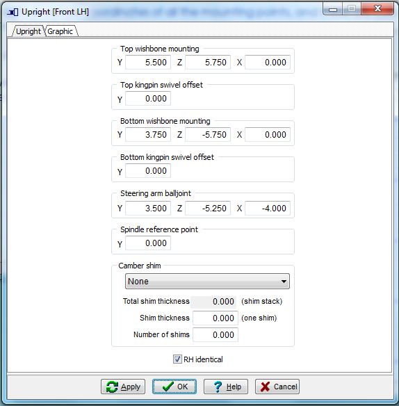
Upright (knuckle design).
The upright top and bottom wishbone mountings are fixed in the demo version.
The top wishbone mounting (upper ball joint) dimensions are: Y 150.00; Z 120.00; X 0.00
The bottom wishbone mounting (lower ball joint) dimensions are: Y 100.00; Z -120.00; X 0.00.
Note that the Z dimension is negative, as it is below the axle centerline.The steering ball joint is not needed for the basic geometry calculations, but they can be entered now.
Enter the steering arm ball joint dimensions: Y 100.00; Z -120.00; X 100.00.
If you can't enter all three steering arm ball joint dimensions then go to Steering and make sure that the steering calculation option is set to [Fixed]; and not [Upright] or [Chassis].Leave the spindle reference point at zero and the camber shim as 'None'.
Make sure that "RH identical" is ticked, then click OK.
Herb's analysis package requires the actual vehicle coordinates of all the mounting points. These are calculated by Herb, but the calculations are not shown in the book.
We will use SusProg3D do all our calculations.
ICs.
As discussed by Herb, we will use a swing axle length of 3150 and a roll centre -5.00 which is just below the road surface. We will use these to determine the height of the wishbone chassis mounting points.
This is where we specify the swing axle lengths and roll centre location.
Specify the front view swing axle length 3150.00, the roll centre height -5.00 and the roll centre offset 0.0.
Specify the side view instant centre length as 9400.00 and the instant centre height 140.00.
Don't worry if the RH values are wrong. Because we will specify "RH identical" the RH values will automatically be updated on "OK" (or on "Apply").
Make sure that "Calculate using" is set to "Height", and "RH identical" is ticked, then click OK.Why specify the side view instant centre height of 140mm?
Basically, it’s a guess. But we know that we want the bottom wishbone pivots parallel to the ground, so that means that the instant center height will be around 140mm. We will use 140mm to do the initial calculations, and then vary it later.

Chassis.
Because we are specifying the swing axle length and the roll centre height, we only need to specify the lateral and longitudinal dimensions of the top and bottom wishbone mounting points.
The vertical dimensions will be calculated from the swing axle and roll centre dimensions.Using Herb's dimensions, the lateral locations will be estimated from the track, upright and wishbone length.
The top wishbone lateral dimension will be 762.00 (half front track) minus 150.00 (the upright top ball joint) minus 206.00 (the nominal wishbone length) giving 406.00.
Specify the top wishbone mounting Y dimensions as 406.00 for both front and rear.
Specify the top wishbone mounting X dimensions as -2.50 and -152.50 for front and rear respectively.The bottom wishbone lateral dimension will be 762.00 (half front track) minus 100.00 (the upright bottom ball joint) minus 262.00 (the nominal wishbone length) giving 300.00.
Specify the bottom wishbone mounting Y dimensions as 300.00 for both front and rear.
Specify the bottom wishbone mounting X dimensions as 35.00 and -255.00 for front and rear respectively.The steering rack ball joint is not needed for the basic geometry calculations, but they can be entered now.
Enter the steering rack ball joint dimensions: Y 310.00; Z 132.00; X 100.00
If you can't enter all three steering arm ball joint dimensions then go to Steering and make sure that the steering calculation option is set to [Fixed]; and not [Upright] or [Chassis].Note that you don't enter the chassis mounting Z values, as they will be calculated from the swing axle instant centers.
Make sure that "RH identical" is ticked, then click OK.

Calc.
Just click the Calc.
This will do all the static geometry calculations, and update the graphic. It should look like this.
Hint:
If the graphic doesn't fill the screen, press "+" key to enlarge the graphic. The "-" key will shrink the graphic.
To keep this enlargement, go to Display and then change [NoHold] to [Hold]

Save. Just use Ctrl-S.
![]()
Have a look at the Chassis dimensions again. Open the Chassis input, and slide it to one side. Notice that the bottom wishbone rear Z value is less than the front Z value. We want them both the same. So this means that we must raise the side view swing axle instant center height. Open the IC input, and slide it to one side. You should be able to see both the Chassis and the IC inputs at the same time.

Change the side view instant center height to 145.00 and then click “Apply”, and then Calc. Notice that the Chassis input has refreshed with the new wishbone mounting Y values, and that the bottom wishbone mounting Y values are now identical.
This illustrates how we can start from the swing axle and roll centre dimensions to establish the wishbone mounting points. Now we will swap around.
Open Config and change from “Swing axle lengths ” to “Suspension link chassis mounting points”. Click OK.
Notice that the Chassis input has updated, and now the Y values can be input. The Instant Centre input has also updated, and now all values are “read only”.

Change the Chassis bottom wishbone mounting Z values to 120.00 (front and rear). Click “Apply” and Calc.
Notice that the instant centre values have also updated. The swing axle length is now 3216.62 and the roll centre height is –7.00. Also the side view instant centre length is now 9397.01 and the height 145.08.

So now you see how to use the chassis mounting points to calculate the swing axle and roll centre values.
Close the chassis and instant centre dialogs and Save.
![]()
Now lets see what happens when the suspension bumps and droops.
Switch to the Roll Bump tab.
Config.
There are three sections in the Roll and Bump Config.
In Bump and droop increments, set the maximum and minimum travel to 100.00 and both bump and droop increments to 20.00
In Roll increments, set the maximum roll to 4.00 degrees and roll to the right, the roll increments to 0.50 (for display) and 0.25 (for calculate) and the initial bump position at “Static”.
In Roll centre and axis, leave the roll centre at “semi-dynamic” and the roll axis at “horizontal”.
Click OK.


Calc.
This will do all the roll and bump geometry calculations.
Results.
Now you can see how the wheel alignment values change as the wheel is bumped and drooped.

Save.
![]()
Now lets see about the bump steer.
Before doing the steering calculations, go to Display -> Control and
"tick" the "toe link", "rack" and
"wheel" in the Show section. The steering
rack and tie rods will now display, along with the wheel and tyres.
Because the steering has not been calculated, the tie rods will be drawn out of
position.
Now switch to the Steering tab.
We had previously entered the steering rack and steering arm ball joint dimensions, so we will use them do the calculations.
Make sure that the steering calculation option is set to [Fixed]; and not
[Upright] or [Chassis].
This means that we will use the specified rack and steering arm dimensions to
calculate the bump steer.
Config.
Set the steering type to “Rack and pinion”; the C-factor to 50.00; the steering gearbox location to either LHD or RHD; and the rack and pinion config type to “1”.
Although we have specified the steering arm ball joint as X = 100 (so that the steering arm and tie rod location is “Front steer”) it may show as "Rear steer". This will correct when the Steering calculation is done.
Click OK.

Toe turn.
Set the maximum turn angle to 30.00 degrees and the increment to 5 degrees.
Click OK.

Calc.
This will do all the bump steer calculations, and update the graphic. It should look like this.

Results.
Open the results, and look at the bump steer values. Note the values at the 100.00 bump and droop positions.
Maybe we can do better.
Close the results.
Change the [Fixed] to [Chassis]. This will calculate a rack position to minimize the bump steer.
Calc, then reopen the Results. Much better.
Notice the new steering rack ball joint position. Slightly more inboard and lower than originally. This highlights the need to ensure that there is some adjustability built into either the rack or the steering arm ball joint mounting.


![]()
Well, that's enough for this tutorial.
We have gone from essentially a blank piece of paper,
to a basic suspension geometry.
The bump steer is pretty good, but the roll
centre control may need a bit of work.
SusProg3D - Suspension by Design
Version 4.84 23/08/2007
|
JOIN
the SusProg3D
Mailing List and be kept informed on the latest developments
We DO NOT
sell, hire or loan names and address to other organizations My
Privacy Policy
 © 2012 Beven D Young All rights reserved


This page was last modified: