
|
[ Home ][ Suspension Types ] [ Tutorials ][ Data files ] [ FAQ ] [ Purchase here ] [ Contact us ][ Join The Mailing List ][ Downlaod SusProg3D ]
Converting 3D Coordinate Measuring Machine (CMM) data to SusProg3D upright dimensions
![]()
Often, vehicle manufacturers and professional car builders are able to provide coordinates for the various suspension points, usually obtained with a very sophisticated (and expensive) 3D Coordinate Measuring Machine. Usually these dimensions are "ground based".
This tutorial is intended to demonstrate the conversion of Coordinate Measuring Machine (CMM) coordinates to the SusProg3D coordinates, specifically to obtain the SusProg3D upright coordinates.
The CMM data supplied for this exercise was provided in imperial dimensions, and was in the following format.
|
Front suspension |
X |
Y |
Z |
|
Wheel centre |
45.879 |
30.594 |
13.633 |
| Axle end point | 45.838 | 25.037 | 13.324 |
| Upper ball joint | 46.572 | 22.626 | 21.116 |
| Lower ball joint | 45.404 | 24.601 | 8.864 |
| Upper A-arm, front pivot | 41.865 | 14.619 | 18.067 |
| Upper A-arm, rear pivot | 51.756 | 14.636 | 17.839 |
| Lower A-arm, front pivot | 45.857 | 8.541 | 7.124 |
| Lower A-arm, rear pivot | 57.922 | 15.061 | 8.362 |
| Chassis frame | |||
| Front frame reference | 71.576 | 28.775 | 6.060 |
| Rear frame reference | 136.623 | 28.845 | 7.219 |
| Rear suspension | |||
| Wheel centre | 155.855 | 30.763 | 13.897 |
The critical requirement, is that the data must provide two data points on the wheel axis. Usually one will be on the wheel centreline, and the other will be on the axle end. These two points will enable all the upright coordinates, wheel alignment (camber and toe), and track to be determined.
You will need SusProg3D, version 4.53A (or later) to get the latest V2U
tools.
This tutorial requires a registered copy of SusProg3D. It will not work
with the evaluation version.
Start SusProg3D.
This tutorial will use imperial units, and a custom axis system to match the supplied data.
Go to Settings -> Settings -> Units. Select Imperial, then OK.
Just by looking at the supplied data, it can be seen that X is the longitudinal axis, with +ve rearwards; Y is the lateral axis, and Z is the vertical axis, with +ve upwards. It is not obvious whether the lateral axis is +ve left or right, so choose which seems more appropriate. I have chosen +ve LH.
Go to Settings -> Settings -> Axis System.
Change the
lateral axis identifier to "Y" and "+ve LH"; the
vertical axis identifier to "Z" and "+ve up"; and the longitudinal
axis identifier to "X" and "+ve rear". Click OK.
Check that the wheel mounting flange dimension is
correctly specified.
Go to Settings -> Settings -> Wheel mounting flange.
Select Offset, then OK.
![]()
Before using the CMM tool, we need to specify the basic vehicle configuration and reference data.
Select the Vehicle tab, then each of the following items in turn.
Config
For the front geometry, choose "Double A-arm". The remainder of the items can be left as-is.
Click OK.
Front Wheel
The only thing we know, is the approximate rolling radius. Assume the rolling radius is the same as the wheel centre height, 13.633". and the toe reference length is 17.000" to match the assumed rim diameter.
Make sure that "identical" is ticked. Click OK.
This has now completed the basic vehicle data. At this point it is probably wise to save the data.
Go to File -> Save As.
Specify an appropriate directory and file name.
At this stage there is no graphic display, other than a small cross in the centre.
![]()
Now we can enter the CMM dimensions.
Select the Tools tab.
We are working with the front suspension, and will input data for the RH side.
The first menu item should be [Front]. If
it is [Rear] then click it, and change it to [Front].
The next menu item should be [LH]. If it is [RH] then
click it, and change it to [LH].
Hint: If the CMM data has one side of the vehicle with +ve lateral dimensions,
and the other side with -ve lateral dimensions, then always use the side that
corresponds to the +ve dimensions. We chose RH because the lateral
dimensions are +ve RH. If you have the lateral axis +ve LH, then choose LH here.
Select the CMM tool, and then the CMM to Strut tab.
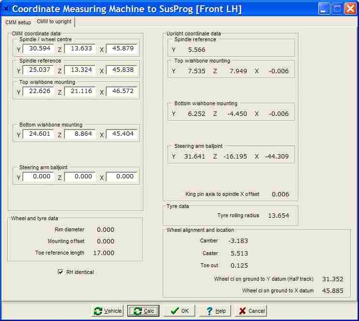
Enter the CMM coordinate data
The spindle/wheel centre dimensions are: Y = 30.594", Z = 13.633", X = 45.879" (Wheel centre)
The spindle reference dimensions are: Y = 25.037", Z = 13.324", X = 45.838" (Axle end point)
The top A-arm mounting dimensions are: Y = 22.626", Z = 21.116", X = 46.572" (Upper ball joint)
The bottom A-arm mounting dimensions are: Y = 24.601", Z = 8.864", X = 45.404" (Lower ball joint)
The steering arm balljoint dimensions not supplied, so leave blank.
Calc.
Just click the Calc.
This will do all the calculations.
The steering arm balljoint dimensions are obviously wrong, but this was because the supplied data didn't include those dimensions.
If the wheel spindle is not on the ball joint axis aka king pin (in side view) then this will be shown as “King pin axis to spindle offset”.
The upright dimensions are all calculated relative to a vertical king pin axis (in side view). In this example, because the longitudinal axis is positive rearwards, the positive value indicates that the spindle is behind the strut rod axis 0.006", hence the strut rod X data points are negative (ie in front of the spindle by 0.006").If "identical" is ticked, then the specified CMM coordinates will be calculated for the opposite side of the vehicle as well.
Hint.
Even if the vehicle is not symmetrical, it may still be quicker to assume that it is, as this will mean that the other side CMM data is set to the same is this side (with the sign change for the lateral dimensions). You can then "swap sides", open a second CMM tool, and then change whichever dimensions are different, without having to reenter all of them.Press Control+S and save the CMM data.
Vehicle
If you want to use these calculated values to update the vehicle data, then press “Vehicle”.
The upright dimensions will be carried over to the Geometry | Upright input dialog.
The tyre rolling radius will be carried over to the Geometry | Wheel input dialog.
The wheel alignment and location will be carried over to the Geometry | Alignment input dialog.If the vehicle is symmetrical, then tick the “identical” box, and then this will update both LH and RH struts.
If the vehicle is not symmetrical, then leave this box unticked. You will then need to switch sides, open a second copy of the tool, and input the CMM data for the other side. Remember that if you are doing the side which is the negative lateral axis, then all the lateral dimensions must be entered as negative.Save the CMM data, use Control+S as a shortcut for File | Save.
![]()
Well, that's enough for this tutorial.
Now we have the upright dimensions, wheel and tyre dimensions, and basic setup alignment.
Now, it is easy to start varying.
What if a smaller tyre is fitted?
What if the camber is changed?
All of this without having to recalculate the world coordinates! And that is the main advantage of having the upright coordinates in their own axis system. The freedom to move and realign.
SusProg3D - Suspension by Design
Version 4.84 23/08/2007
|
JOIN
the SusProg3D
Mailing List and be kept informed on the latest developments
We DO NOT
sell, hire or loan names and address to other organizations My
Privacy Policy
 © 2012 Beven D Young All rights reserved

